
most common failures in RF circuit boards
PCBs are essential for a wide range of applications. From enabling wireless communication to facilitating advanced radar and sensing systems, these critical components are responsible for driving technological advancements across industries. Despite their pervasive nature, RF circuit boards are often subject to failures. Fortunately, understanding and avoiding the most common failures can help you avoid costly mistakes and ensure the highest quality in your product.
When a rf circuit board fails at the board level, it is generally due to one or more mechanical stresses caused by vibrational or bending activity. This can cause the board to break down or experience significant signal loss, which could impact the operation of the device as a whole.
Typically, thermal damage occurs when there is a defect in the thermal connections between layers of the board. These defects can be caused by issues in the manufacturing process, such as faulty molding or over-machining, and can result in a reduced connection between the board layers. This can lead to overheating and heat damage, which will eventually deteriorate the board.
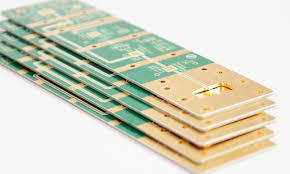
What are the most common failures in RF circuit boards?
When an RF circuit board isn’t properly matched, it is prone to power losses and poor performance. RF circuits are highly sensitive to the impedance of their connecting lines, so it is important to choose the right wire type and route them carefully. For example, a digital circuit shouldn’t be routed close to an RF signal, as this will introduce coupling between them and cause signal noise or interference.
RF signals are more prone to noise and interference from other circuits than digital circuits, so it’s important that RF signal lines do not run over the power and ground planes on the circuit board. For this reason, it’s a good idea to add multiple ground vias to the board. This will prevent ground inductance from leaking between the traces, and it will also help to reduce cross-coupling between RF signal lines.
In order to prevent overheating, it’s necessary to decouple the power supply from RF components. This can be accomplished by using a “star” route for the power-supply connections, with a large decoupling capacitor at the center of the star and smaller capacitors placed on each branch of the star. The value of these smaller capacitors will depend on the operating frequency of the RF IC.
These are just a few of the most common failures in RF circuit boards. By being aware of these common mechanisms, engineers can better understand how to design and manufacture high-performance RF circuits that will meet the needs of today’s most sophisticated devices. Additionally, awareness of these mechanisms can help to drive improvement in designs, manufacturing processes, parts, and testing methods for greater reliability and quality. Rigorous PCB failure analysis helps to improve products and boost company profits. To learn more, download our free whitepaper.